The Challenges of Measuring Flare Gas

flare gas measurement

The associated gas generated from oil production has received a lot of attention recently. In many areas, the lack of gas collection infrastructure requires this gas to be flared off. Many jurisdictions now require flare gas monitoring in order to reduce emissions and to allocate taxes, fines, and other fees. Choosing the best tools for flare gas measurement can be a challenge, however, and there are a number of potential options on the market.

Below, we examine flare gas and why selecting a good measurement solution can be a challenge for oil and gas companies. Then, we explore the technologies available for flare gas monitoring and the pros and cons of each option.

Understanding Flare Gas Monitoring

Oil extraction processes such as hydraulic fracturing produce excess natural gases. Those gases need to be dealt with carefully, so they do not cause dangerous pressure increases at extraction sites. Harvesting the gases for other uses is not always possible due to cost and infrastructure challenges. 

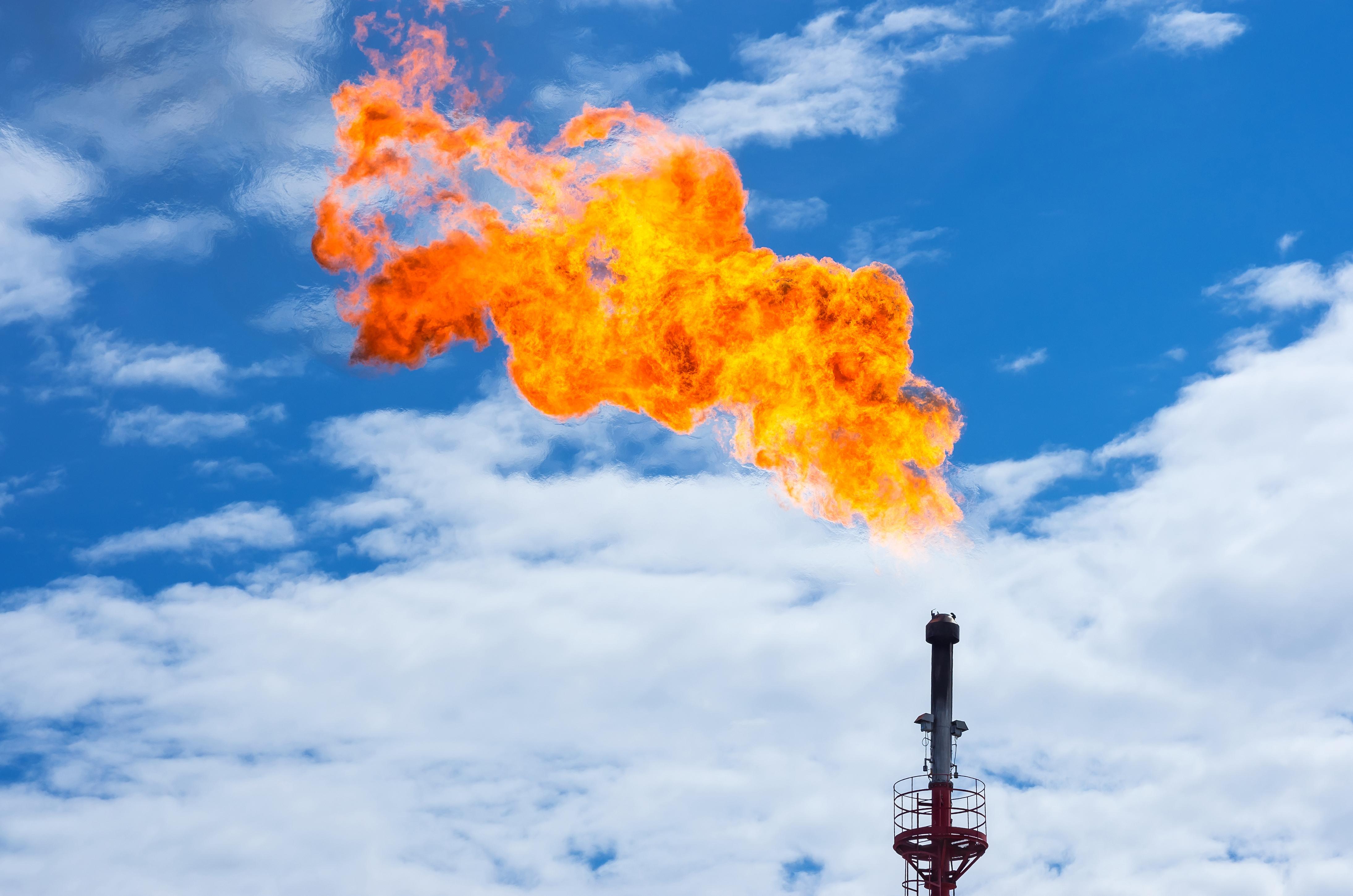
To get rid of the excess gas safely and efficiently, oil and gas companies use a process called “flaring” that burns it off.

The flaring process produces soot and carbon dioxide as gases are combusted. Those byproducts lead to environmental impacts when entering the atmosphere.  

Increasingly, government organizations have set rules that require oil and gas companies to measure exactly how much gas is being flared. Investing in accurate, cost-effective measurement solutions is an important step for those companies to monitor greenhouse gas contributions and avoid costly fines.

Measuring the flow rate of flare gas is challenging because a flare is not a pure gas but a mixture of many different gases. 

In order to correctly measure the total flare flow rate, the composition of the flare must be known.  This is typically determined by taking a sample (a cut) and processing it through a gas chromatograph (GC).

Once the gas begins to flow from a well, operators need to account for this associated gas from day 1.  This need requires a flow meter calibrated to measure the flow rate of the flare gas.  

Virtually all current flow measurement technology requires a known composition for calibration.  This presents a “chicken or egg” problem since the composition may not be known at start-up and will change over time. In many cases, a flow meter may be rendered inaccurate at best and inoperable at worst. 

Below are some common solutions that oil and gas companies use to try and overcome that challenge.

Flare Gas Measurement Tools

Ultrasonic Flow Meters

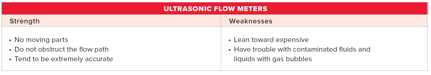
Multi-path ultrasonic flow meters have been a common solution for applications with changing gas compositions.  These meters are built into in-line pipe sections and measure the speed of sound through the flare gas to measure its density.  

Ultrasonic flow meters are used in flare gas measurement because the technology works despite the changing gas composition characteristic of flare gas. The meters are also less likely to get clogged or dirty since they are not directly exposed to the flare gases, leading to reduced maintenance costs. 

Another important feature of ultrasonic flow meters is that they measure mass flow instead of volumetric flow, providing more accurate readings through factors like temperature changes.

On the downside, the entire meter must be removed if pipe sections need to be cleaned. This process can lead to accuracy problems over time. Swirl and other flow profile effects can also influence the accuracy of ultrasonic flow meters.

Lastly, ultrasonic flow meters are an expensive solution. These meters compute flow rates using multiple paths with more paths translating to better measurements. Each of those paths adds to the cost of the meter and can make ultrasonic flow meters a costly investment.

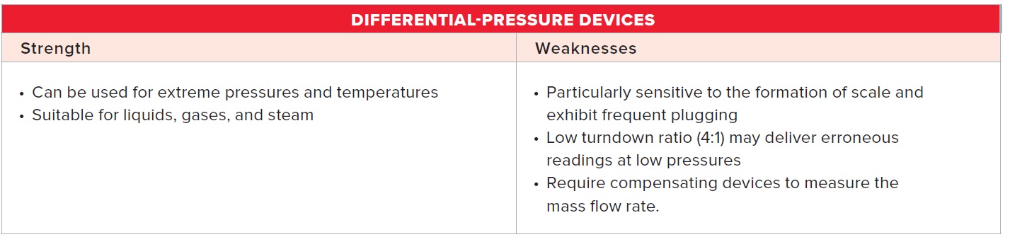
Averaging Pitot Tubes

Averaging pitot tubes may also be used for flare gas monitoring. These tubes work by placing an obstruction directly in the gas flow and measuring the differential pressure of the flow on each side of the obstruction. 

The benefit of averaging pitot tubes is that they measure average across the pipe rather than at one point. They are also a relatively inexpensive option.

Averaging pitot tubes are not an ideal solution for flare gas measurement, however, because they measure volumetric flow instead of mass flow. That key difference can impact the accuracy required to meet key government regulations. Averaging pitot tubes are also highly-prone to clogs and other issues since they are exposed directly to the gas flow. They have poor high and low flow (turndown) capabilities and are unable to measure changes in gas composition changes. 

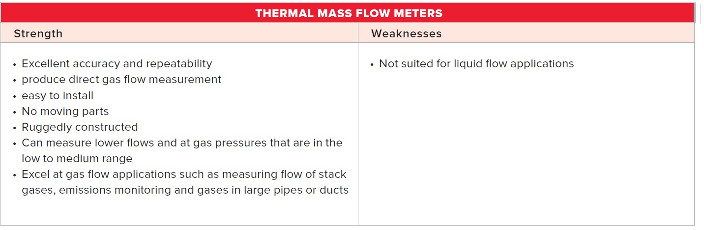
Thermal Gas Flow Meters

Traditionally, thermal gas flow meters have not been a good fit for flare monitoring because they require factory recalibration when gas composition changes. However, new advancements in thermal gas flow meter technology have overcome that obstacle, and thermal gas flow meters have emerged as a viable solution for flare gas measurement.

An important feature that makes thermal gas flow meters suitable for flare gas monitoring is that they can meet or exceed EPA CFR 40. Advanced thermal gas flow meters also remain highly accurate even when gas composition changes. Like ultrasonic flow meters, they measure mass flow for improved accuracy but also have additional benefits for flare gas measurement.

Sierra’s QuadraTherm® Flow Meters for Flare Gas Monitoring

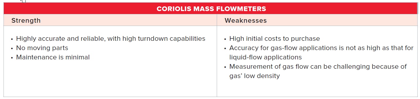
Recent innovations in immersible thermal flow meter technology provide a solution to the “what came first” problem outlined above.  Sierra’s QuadraTherm flow meter can accurately measure the mass flow of gases over a very wide turn-down. 

Most importantly, users can change the meter’s calibration in the field to reflect the actual gas composition thanks to an industry-first algorithm called qMix™. This technology uses the NIST RefProp database of gases to calculate the heat transfer properties of complex gas mixtures and thus maintains meter accuracy.

qMix™ Mathematical Model – How It Works*

QuadraTherm’s advanced mathematical model operates a microprocessor-based system that provides the foundation for making in-the-field compositional compensation.

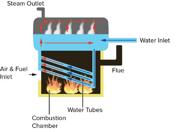
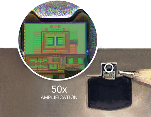
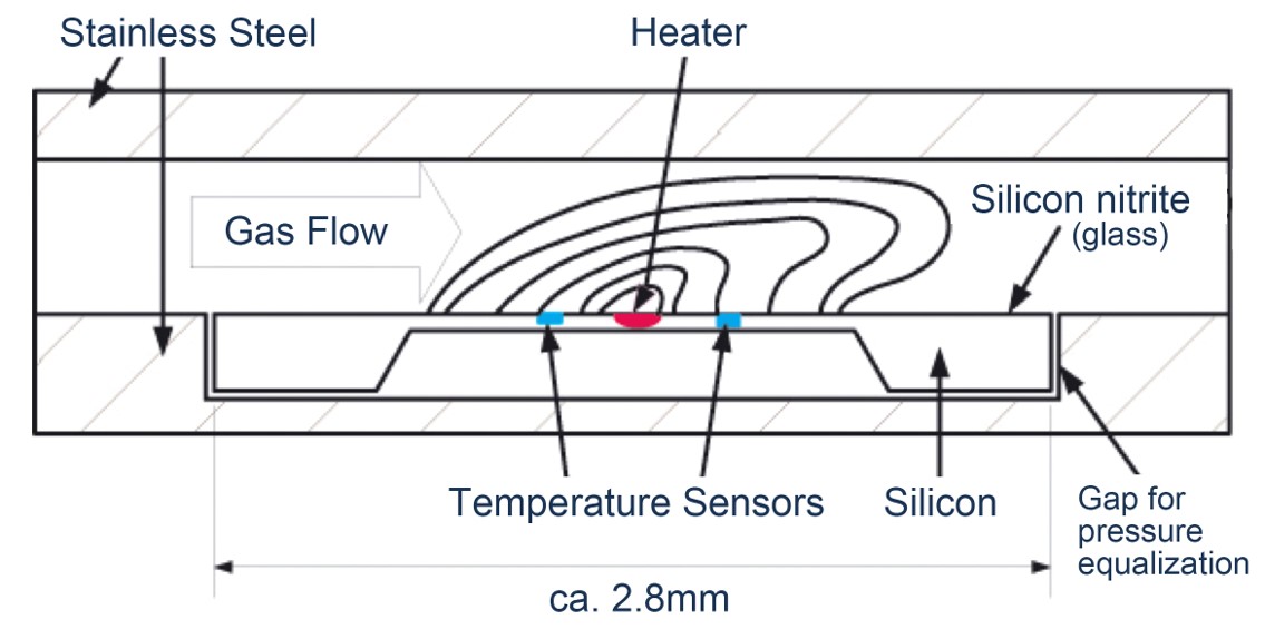
In a thermal mass flow meter, a velocity sensor measures the heat removed from a heated sensor by the flowing gas. Additional sensors measure other heat losses, such as those caused by natural convection, radiation, stem, and end loss. The heat removed by the flowing gas is proportional to the mass flow.  

In operation, the four-temperature microprocessor-based system measures the resistance of each of four RTD sensors along with the current in the velocity sensor. The resistance values are converted to their four corresponding temperature values. The current to the velocity sensor is also converted to electrical power or wattage. 

The four temperatures, the wattage, and the gas composition are the inputs to the system. The gas property algorithms calculate the updated properties of the gas (mass density, dynamic viscosity, thermal conductivity, and heat capacity). The system then computes the total mass flow rate in the pipeline – the desired output.

QuadraTherm meters can thus be stocked on the shelf, ready to go when a spare or new meter is needed. They can be installed easily and the sample gas composition programmed upon start-up of the well, thus ensuring day 1 flow measurement accuracy.

Selecting a Flare Gas Measurement Solution

These features demonstrate how Sierra’s QuadraTherm® flow meters have emerged as the clear frontrunner for flare gas measurement. Wide turndown, direct mass flow measurement, and advanced day 1 accuracy make QuadraTherm® meters the most accurate and economic flare gas measurement tool for oil and gas applications.

See our flare gas flow meter options and benefits.

Download “New Developments in Thermal Dispersion Mass Flow Meters: In-The-Field Compensation for Changes in Natural Gas Composition” for more information on advances of QuadraTherm with qMix.

*Reference: Blog copy reprinted from Olin, J. G. 2014. New Developments in Thermal Dispersion Mass Flow Meters: In-The-Field Compensation for Changes in Natural Gas Composition. Presented at 2014 American Gas Association Operations Conference, Pittsburgh, PA, May 20-23, 2014.


Understanding Flow Measurement for Emissions Monitoring

Take Charge of Your Boiler Efficiency & Avoid Steep EPA Emissions Fines
Sounds like an impossible task, but it’s not.

Emissions monitoring is a hot topic for plant and facility managers due to the elevating importance of three factors:

  1. Global climate-change mitigation efforts
  2. Increasing governmental regulations
  3. Social pressures

Due to this, there is also a heightened importance to accurately measure gas flow for high boiler and process-heater efficiency.  Why? Because accurate flow measurement is critical to achieving boiler efficiency.

Measuring Flow in Your Boiler

In emissions control and combustion applications, flowmeters are used to measure the flow of fuel gas (normally natural gas) and air to combustion burners within various types of process equipment to maintain a fuel-to-air ratio that will maximize efficiency while producing minimal pollutant products. Ratios that are either too rich in natural gas, or too lean, will result in unnecessary emissions and wasted fuel.

boiler

Flow measurement technologies can be used in industrial boilers to monitor the air and fuel inlet, as well as the water inlet and the steam outlet

If the flow of gaseous combustion products — including greenhouse gases like carbon dioxide, carbon monoxide, nitrogen oxides (NOx) and unburned methane — as well as the fuel input, can be measured accurately, users can gain a full picture of the boiler’s efficiency. Accurate measurement of steam production determines whether a boiler is producing the expected amount of steam for the fuel input, or if the boiler needs to be tuned for increased efficiency.

What is Boiler MACT?

Large facilities like petroleum refineries and chemical manufacturing facilities with boilers and process heaters  must meet emissions requirements established in the National Emission Standards for Hazardous Air Pollutants (NESHAP) for industrial, commercial, and institutional boilers and process heaters standards, issued by the EPA which are based on Boiler MACT.

Boiler MACT (Maximum Achievable Control Technology) is an EPA rule to limit hazardous air pollutants (HAP) from commercial and industrial boilers and process heaters.  Driven by the Clean Air Act, the rules are Area Source Boiler MACT 40 CFR 63, subpart JJJJJJ for smaller boilers (stores, hotels, apartments, small manufacturers, etc.) and Major Source Boiler MACT subpart DDDD for large boilers (petroleum refineries, chemical and large manufacturing plants, large facilities).

The rules require two things from manufacturers:

  1. Facilities must monitor the amount of emissions of carbon monoxide, particulate matter, mercury, HCl, and other pollutants.
  2. Requires end-users to “tune” new boilers when they first start up, and then perform periodic tuning to measure the boiler’s efficiency in combusting the fuel and turning the water into steam.

Tuning Your Boiler

Tuning a boiler or process heater involves inspecting the flame pattern and adjusting the burners, as well as inspecting the system that controls the air-to-fuel ratio to ensure it is correctly calibrated and operating properly. Facilities that tune their boilers to ensure the maximum boiler efficiency can simultaneously minimize the amount of air pollutants generated.

A well-tuned boiler is 80% efficient.  If your boiler is less than 80% efficient then you are wasting energy and releasing hazardous air pollutants into the environment unnecessarily.   Improving the suboptimal efficiency could involve repairing leaks, adding insulation and cleaning heat exchanger tubes.

Highly efficient boilers and process heaters minimize the release of greenhouse gases, and accurate flow measurement is an essential part of achieving high efficiency. Flowmeter manufacturers with Boiler-MACT-compliant devices are capable of measuring the combustion gases produced.

Flow Measurement Technologies to Improve Boiler Efficiency

Flowmeters can help meet Boiler-MACT emissions limits and there is a wide range of technologies available for the measurement of gas flowrate in closed pipes for applications involving combustion and steam. Flowmeters can be categorized in several ways, but one approach is to divide them into four classes: mass, velocity, differential pressure, and positive displacement.

Available technologies include:

Key parameters for assessing the effectiveness of a flowmeter device include accuracy, durability, maintenance, and total cost of ownership. The different strength-and-weakness profiles for flowmeters partly depend on the requirements of the application, including whether the fluid being measured is a gas or liquid.

For this blog’s purposes, we are going to look at some of the available flow technologies.

Strengths and Weaknesses of Available Flow Measurement Technologies to Improve Boiler Efficiencies


The Best Choice for Optimizing Your Boiler Efficiency

For gas-flow applications, thermal mass flowmeters often emerge as the best choice. The newest models of thermal mass flowmeters are often able to overcome the limitations of previous models. For example, the accuracy of Sierra’s QuadraTherm thermal mass meters rivals that of Coriolis meters, but at lower prices. In addition, thermal mass flowmeters have wider application flexibility, and the efficiency and capabilities of the latest thermal mass flow meters have been enhanced to include better turndown ratios, minimal pressure drop and the ability to install the instruments without having to shut down a process.

Learn more about flow measurement for emissions monitoring and improving your boiler efficiency, download our new white paper “Understanding Flow Measurement for Emissions Monitoring.”

For more information about tuning your boiler, watch our “3 Tips to Improve Energy Efficiency” video or read or our previous blog, “Tuning Your Boiler for EPA Boiler MACT Compliance.”


Simplify The Flow Meter Selection Process with Sierra Instruments’ New App

Need to measure flow but don’t know what type of flow meter you need? Our new app gives you the answers-quickly and easily.  Sierra Instruments is excited to announce the launch of our new flow meter selection app to simplify the flow meter specification process.

Our new app helps you find the right flow meter for your application in just a few clicks. Sound too good to be true? It’s not. We know specifying a flow meter is not easy becausee one size flow meter does not fit all. Accurate flow meter specification depends on many variables like desired accuracy, flow rate, temperature, pressure, gas type, pipe, or fitting size.

Select Your Perfect Flow Meter with Four Simple Questions

Launch the app by clicking the “Select a Meter” button on the home page. The new app will then run through a logical sequence of essential questions needed to quickly specify the correct flow meter for your application:

  1. What fluid are you measuring-gas, liquid, or steam?
  2. Estimated flow rate?
  3. Pipe or fitting size?
  4. Hot tap requirements?

With your answers, our new flow meter selection app will serve up tailored flow meter product recommendations for your application. The app also integrates Sierra’s online store into the results to give you the option to buy online for fast delivery. If you become stuck, connect easily with Sierra’s flow experts to get answers to your questions.

Try the flow meter selection app today and see for yourself how it works.


How Do MEMS Mass Flow Controllers Work?

Not All MFC Sensor Technology is Created Equal

Mass flow controllers offer precision gas flow control to many critical industries including biopharm, semicon, food & beverage, manufacturing, and R&D. As the technology demands increase in these sectors, so does the demand for precision gas flow control systems. The more accurate and repeatable the gas flow control the better the yield, the higher the product quality and the lower the cost in wasted materials.

So what mass flow control technology offers the highest accuracy and repeatability over time? MEMS (Micro-Electro Mechanical Systems) sensors offer the most stable and accurate gas flow control in the industry. Mass flow controllers and meters based on MEMS technology don’t drift like other technologies, offering OEMs and bioprocessing applications a mass flow controller that is accurate over the lifetime of the device-no yearly recalibration or process shutdown necessary.

How does MEMS technology work to ensure a “no-drift” mass flow controller?

MEMS Principle of Operation

MEMS technology utilizes an advanced, ultra-stable, no-drift CMOS (Complementary Metal Oxide Semiconductor) sensor. The CMOS sensor houses both the electronic circuits and mechanical elements on a silicon chip, similar to the process used for integrated circuits.

Sierra’s RedySmart MFC – MEMS Sensor at 50x Amplification view

MEMS technology is based on the thermal principle of operation. MEMS sensors consist of two or three temperature sensors and a heater. Through vapor deposition, an extremely small molecular layer is deposited on a thin membrane. MEMS-based mass flow controllers have a bypass that pushes a defined percentage of the total gas flow through the sensor. The bore of the sensor is fairly large, so that the pressure drop is relatively low. In the presence of flow, the MEMS chip introduces heat into the medium with a constant heating output. The two temperature sensors are arranged symmetrically before and after the heating element to detect a shift in the temperature profile towards the downstream sensor of the heating element. If there is no flow, both sensing elements measure the same temperature. Because the sensor is part of the MEMS electronic circuit, the measured signal is immediately digitized giving direct mass flow readings.

Why Mass Flow is Critical

Measuring mass flow is important since most processes are more directly related to mass flow rather than to volumetric flow. For respiration, fermentation or any chemical process, it is that number of oxygen molecules that are critical, mass not volume that is critical. Unlike turbine meters, ultrasonic, pressure differential, pitot tubes and many other devices, thermal flow meters measure mass flow. Direct mass flow meters are unaffected by fluctuations in both temperature and pressure which make them inherently more accurate than volumetric technologies.

Benefits of MEMS Mass Flow Controllers

The biggest advantage of the MEMs sensor is that there is no (measurable) drift. Drift is a slow shift of the zero and the measured value at a given flow. Drift affects the accuracy. MEMS sensors are also compatible with its electromagnetic (EM) environment and don’t emit levels of EM energy that cause electromagnetic interference (EMI) distorting the signal. This along with the fact that the sensors are free of mechanical and thermal stress enables a no drift sensor and long-term device accuracy.

Mass flow controllers based on MEMs technology do not have a linear output, so they must be calibrated with the actual gas that is being used in the application. The output is a complex curve that can only be accurately curve-fit with a spline or a polynomial. And every sensor construction varies, so there is no repeatability from sensor to sensor. That means that every flow meter and controller needs to be calibrated individually on actual gas which increases their accuracy.

MEMS sensors are also very fast with a 50 msec response time with virtually no warm-up time. The instrument does not need the zero to be adjusted on regular basis. A MEMS sensor is also a lot more sensitive and due to that a turndown of 1000 : 1 is obtainable.

Benefits of MEMS Sensors

  • No-drift sensor-Long term stability over a long period of use
  • Wide turndown of 100:1. (Higher possible)
  • Less sensitive to pollution due to big ID sensor
  • Excellent temperature coefficient
  • High accuracy due to real gas calibration
  • Low-pressure drop (2.5 mbar at low flow)
  • Built-in flexibility
  • Low power consumption

RedySmart Mass Flow Controller with Lifetime No-Drift Sensor Warranty

Sierra’s RedySmart thermal mass flow meters & mass controllers are based on MEMS-based (Micro-Electro Mechanical System) technology to complement our SmartTrak® capillary-based mass flow meters & gas controllers. RedySmart thermal mass flow devices contain no moving parts and are unaffected by upstream temperature and pressure fluctuations, resulting in exceptional accuracy and repeatability.

RedySmart Proven & Stable Mass Flow Controllers offer OEMS:

  • Lifetime no-drift sensor warranty – if drift occurs, instrument will be repaired or replaced free of charge
  • High Accuracy up to ± 0.3% of full scale ±0.5% of reading
  • Repeatability of +/- 0.2% of full scale
  • Air, N2, O2 are standard. Other non-toxic, non-corrosive gases available upon request.
  • Custom and compact gas mixing blocks
  • MEMS (Micro-Electro Mechanical Systems) with ultra-stable no-drift CMOS (Complementary Metal Oxide Semiconductor) sensor
  • Ideal for OEM Applications-optimized for BioPharm/Burner Control
  • Modular-customize to needs. An easy-connect communication and power cable system has been designed for ultimate flexibility

Learn more about MEMS Sensor technology and RedySmart products.

Discover how MEMS sensor technology is providing edge to accelerate bioprocessing from pilot to production.

Top Blogs of 2020

Even though 2020 has come and gone, we would like to take a minute to recognize our Top Blogs from 2020.  As with most things in 2020, the theme of  “get back to the basics” resonated with our readers.

The winning blogs of 2020 all answered foundational questions like: “How does this work?” or “How do I do this?” Enjoy getting back to the flow basics.

Top Blogs of 2020 – Answering Your Top Questions

  1. What Is a Flow Rate Totalizer & How Does It Work?
    Discover how to correctly use flow meter totalizers and understand the power of the iSeries flow meter totalizer in the number one read blog of 2020.
  2. How do Ultrasonic Flow Meters Work?
    Get an in-depth understanding of how ultrasonic flow meters work and why you might choose one for your application.
  3. How a Vortex Flow Meter Works?
    This blog gives explains how vortex flow meters work and the various vortex sensor technology available for steam flow measurement.
  4. Tips & Tricks to Installing Your Flow Energy Meter
    Get practical hands-on advice on how to properly install your flow energy flow meters in this blog. To get an accurate measurement, proper installation is key. Most of the time when your flow meter “doesn’t work,” it could be that your flow meter is not installed properly.
  5. How do Water Flow Meters work?
    One of the most common applications and biggest markets out there is water measurement so it’s no wonder that our blog on how water flow meters work was a top read. Discover the four types of flow meter technologies for water applications and how they work today.
  6. How to obtain perfect gas mixing and blending?
    Offering a complete Guide to Gas Mixing and Blending, this blog dissects this challenging application and discusses how to obtain perfect gas mixing and blending with capillary thermal mass flow controller technology.
  7. Why mass flow instead of volumetric flow?
    Watch this quick tip-video blog to find out the difference between direct mass flow and volumetric flow technology and discover the advantages of direct mass flow.

More To Come In 2021

In 2021, you can expect in-depth content from Sierra Instruments that focuses on “how-to” content to achieve accurate flow measurement, increase energy efficiency, and save money on energy costs.

Welcome to 2021! Let’s make it an amazing year.

Avoid Common Flow Meter Installation Mistakes to Optimize Flow Meter Performance

In our last blog, we discussed how plant and operation managers are searching for ways to manage the flow energy in their facility to cut costs and increase their process efficiency.

After the purchase decision is made, correct installation and calibration are the next steps to maintaining the equipment over the lifetime of the product and lowering the cost of ownership to increase the cost savings of the facility overall.  Let’s look at three common installation mistake to avoid and other ways to ways to lower cost of ownership and optimize your flow meters’ performance.

Avoid Common Installation Mistakes

Once you have identified the right flow meter for each type of fluid and application, proper installation of your flow meter is critical for successful flow readings.  Many times, if you think your flow meter “doesn’t work,” it could just be that the meter was not installed properly.  Here are some installation tips for thermal mass, vortex, and ultrasonic flow meters:

  1. In order to achieve accurate and repeatable performance for thermal mass flow meters, install the flow meter using the recommended number of straight-run pipe diameters upstream and downstream of the sensor. The chart below shows basic good plumbing practice for common upstream obstructions and meter locations.

Another solution for insertion flow meters is to install flow conditioning plates in the flanges somewhere in the straight section, requiring three diameters of pipe run (two before, one after). This installation will totally disrupt the flow, creating a “flat” profile.

2.  Avoid the following mistakes when installing vortex flow meters:

    • Not having the proper upstream and downstream diameter. Unlike thermal flow meters, vortex meters do not work with flow condition plates, so they must have a straight run of pipe to function at optimal levels. In most installations, you need a straight run of at least 10 diameters upstream and 5 diameters downstream.
    • Installing the vortex meter backward. When installing a vortex flow meter, make sure the orientation of your meter is in the direction the flow, so your meter’s flow sensor can measure your fluid accurately. Most vortex flow meters have some type of flow direction indicator to help you point downstream.
    • Measuring the incorrect fluid type in the pipe. In some situations, an end user might be measuring steam flow and think they are producing saturated steam, but in fact, they have a 50% over heat and are measuring superheated steam. (add link to blog explaining this)
    • Don’t shutdown your steam flow to install a vortex flow meter. Many insertion vortex flow meters have a retractor to make hot tap installation much easier. This means you can install the insertion vortex flow meter in large steam pipes with no process shutdown.

3. For ultrasonic flow meters, consider clamp-on sensors for field flexibility and offer for easy setup. With a portable ultrasonic flow meter, you can use one in several locations throughout your flow process. Fieldwork calls for flexibility in your equipment. Look for a liquid flow meter clamp-on sensors with a high-powered ultrasonic pulse and digital signal processing that requires just one set of transducers for a wide range of pipe sizes and materials like metal, plastic, and concrete.

In-Situ Calibration Increases Throughput & Avoids Costly Shutdowns 

The measurement accuracy of your device is critical in determining efficiency, performance, and cost-savings. So the more accurate your flow meter is the better data you have to make cost saving decisions.  Thermal mass flow meters with in-the-field in-situ calibration validate the meter’s accuracy without shutting down the facility. Learn how In-Situ calibration works in this video.

Learn more about how to manage the flow energy in your facility.

Download Flow Energy Guide for additional details on managing flow energy in your facility.

Watch Videos on how to measure air, gas, and steam better in your facility.


How to Choose the Perfect Flow Meter to Reduce Flow Energy Costs in Your Facility


It’s almost October and Fall is in the air. 2020 has turned out to be a tumultuous year and things seem to only be heating up. COVID-19 continues to be a daily factor in our lives, civil unrest is abundant, and the US economy remains volatile.

However, despite these obstacles, common among all manufacturing is a desire to optimize business processes, cut costs where they can, and keep the doors open while still providing the best possible service for their customers. A tangible way to do this is to focus on managing the flow energy in their facility to control costs, increase process efficiency, improve profits. And this all starts with providing facility operations managers and engineers the most accurate flow data to make informed, smart decisions about how to better manage the flow energy in their facility.

Here are some steps to identifying the flow energy applications in your facility, asking the right questions, and then specifying the correct flow meter for the fluid and application to get the most accurate flow measurement possible.

Step 1. Understand Your Plants’ Key Flow Energy Applications and Ask the Right Questions.

The key to getting the best data to manage your facility is to know your plants key flow applications. Common applications across many facilities are natural gas measurement, compressed air measurement, steam production, usage, and allocation, water and energy BTU measurement. The common denominator is all of these are flow processes that need its specific flow energy measured.

Application #1
Precise Natural Gas Measurement-Improve Boiler Efficiency/ Sub-Metering

Need to measure fuel gas flow over a wide range? A single thermal mass flow meter can measure very high flows at peak demand or very low flows during startup and shutdown to always assure the best fuel to air ratio in your burners and boilers. Additionally, thermal mass flow meters can help you to control natural gas costs with sub-metering that will deliver improved accuracy and substantial savings.

Key Questions to control costs and improve process

  • Are your boilers running efficiently?
  • What’s the inlet flow rate of natural gas to your boiler?
  • How can you accurately measure your flow over a wide flow range?
  • If temperature or pressure change in your line, how do you maintain an accurate flow rate?
  • What flow meter technology is best for natural gas measurement?

Application #2
Compressed Air Measurement-Identify Costly Leaks & Inefficiencies
Want to be convinced that the energy costs to generate your compressed air don’t go to waste? Thermal mass flow meters are ideal for detecting compressed air leaks. Due to their low flow sensitivity and compact insertion probe design, you can easily move from place to place to find and eliminate leaks when you see flow where there is no air demand.

Key Questions to control costs and improve process

  • How much compressed air are your air compressors producing?
  • How much compressed air is being allocated to other processes?
  • Are there compressed air leaks in the system?

Application #3
Steam Flow Measurement-Production, Usage, and Allocation
Concerned that pressure drop in your delivery system is affecting your steam flow? Multivariable vortex flow meters measure steam pressure, temperature and mass flow with one compact meter, so you have confidence your steam plant and delivery system are efficient.

Key Questions to control costs and improve process

  • How much steam are your boilers producing?
  • Is your steam pressure drop affecting your flow measurements?
  • How can you measure steam in large pipes without shutting down your operation?
  • When pressure or temperature change, how do you know if your steam flow measurement is still accurate?
  • How much steam are you allocating to each part of your facility or campus?
  • Do you have a steam leak?

Application #4
Water Measurement & Energy BTU Measurement-Optimize Energy Efficiency
Water supply and usage has a significant impact on costs. Measure every drop without cutting a single pipe with a clamp-on ultrasonic flow meters. Integrated temperature measurements know how many BTUs your hot or chilled water loop actually delivers.

Step 2. Find the Right Flow Meter to Accurately Measure Your Key Gas, Liquid and Steam Flows

This is easier said then done. With all the various applications, it is a challenge to find the right flow meters for these gas, liquid, and steam applications. Often many different technologies are needed depending on the type of fluid being measured and many different flow meter companies must be used. Dealing with different companies and technologies can be very time consuming, expensive, and ultimately frustrating.


Sierra has solved this issue with our Big-3™ flow energy management strategy. We manufacture one complete family of flow meters we call the iSeries which work as a team to handle nearly any flow application found in industry. They provide a complete flow solution spread across three technologies, Thermal, Vortex and Ultrasonic. They feature user friendly apps and share a common user interface, so facility managers don’t have to re-learn each meter.

Regardless if you opt for the Big-3 option or just pick and choose one or two types of technologies for your process, the meters should:

  • Have high Accuracy and repeatability
  • Ability to measure a wide flow range – meters than can measure low to high flows.
  • Have Digital Communications Options
  • Calibrated to NIST standards
  • Able to validate in the field for easy in-situ calibration ( thermal/ vortex meters)
  • Have the necessary capabilities to measure flow rates required by governmental regulations

Work with one flow energy management expert that can help ease the burden of specifying new meters and recommissioning.

Our Big-3™ flow energy management strategy gives managers a best case scenario to deal with one flow meter company to specify and support instrumentation for all your gas, liquid, and steam flow measurements. This means one point-of-contact for product specification (measurement goals, fluids, flow rate, turndown requirements, temperature and pressure) and installation, one operating system for easy integration, and one local support team over the lifetime of the product.

Sierra’s Big-3 includes:

Download Flow Energy Guide for additional details to managing flow energy in your facility.

Watch Flow Energy Videos to learn more about how to measure e air, gas and steam better in your facility.

Mass Flow Controllers Support Ventilator Testing

Precision Mass Flow Control Validates Ventilator Accuracy

It’s actually a life and death matter, and we take this very seriously. Accurate mass flow control is crucial in the process of validating the accuracy of oxygen flow for mechanical ventilators and respiratory medical equipment. Ventilators are designed to pump oxygen into a patient that is breathing insufficiently or unable to breathe on their own. A ventilator machine moves air into and out of a patient’s lungs to ensure their body receives the oxygen it needs to survive, and hopefully recover from the effects of the COVID-19 virus.1  To make sure patients are getting the exact amount of oxygen needed, in the field ventilators must be meticulously validated to each flow range in order to be effective.

Proven & Accurate Testing for Respiratory Equipment You Can Trust

With over 20 years of proven performance, Sierra is known for providing scientists with precision mass flow control and the ultimate lab research flexibility.  Every Sierra SmartTrak 100 has a wide operating flow range and pressure requirements and is pre-programmed for up to 10 gases that are field selectable. Because of this, Sierra’s SmartTrak is used as a validation standard in order to verify that the ventilators are performing within specification. For ease of use, scientists can easily change set points, flow rates, engineering units on directly on the push-button display or remotely with the Pilot Module. For particularly challenging applications, Sierra’s dedicated engineering team can provide custom engineering solutions to meet precise customer requirements.

The heart of the SmartTrak 100 mass flow controller is a platinum-wound capillary sensor that directly measures thermal mass flow. Sierra’s patented laminar flow element eliminates non-uniformities and conditions the flow in the capillary sensor into stable laminar behavior where mass flow measurement occurs.

Key SmartTrak 100 Features

  • All clean gases including toxics and corrosives
  • Accuracy – Standard: +1.0% of full scale, High Accuracy – Up to +0.5% of full scale
  • Repeatability – +0.2% of full-scale
  • Multi-Gas – Preprogrammed for up to 10 gases – Field selectable
  • Flow Range – 0 to up to 1,000 slpm
  • Local/remote display and pushbutton interface
  • Buy Online-Fast Next Day delivery

Learn how Sierra’s mass flow controllers are used to accelerate Bioprocessing from Pilot to Full-Scale Production.


 Resources

  1. Sonas Home Health Care, June 28, 2018,  “What is a Mechanical Ventilator?” https://www.sonashomehealth.com/medical-ventilator/ .

New From Sierra, MEMS-based Thermal MFC’s Set the Long-Term Stability Bar – High!


We have been in the capillary thermal mass flow business for nearly 45 years, many have asked us why we recently introduced MEMS thermal mass flow controllers into our product offering.  Combining superior physics, high reliability, and unparalleled flexibility, our new Sierra MEMS-based RedySmart brand mass flow controllers complement our Sierra Capillary-based SmartTrak brand mass flow controllers.

Unparalleled Stability


Our RedySmart MFC targets the Biopharm industry where historically, Sierra did not have a product with a perfect fit.  Biopharm OEMs appreciate the modularity, compact size, and price of the RedySmart MFC.  The incredible long term stability is probably the biggest factor.  Making a big statement in the industry, all Sierra MEMS devices, including RedySmart and RedyCompact, come with a Lifetime No-Drift Sensor Warranty for long-term peace of mind for end-users that will rely on these devices for top results.  Sierra is the only company in the industry to stand behind MFC sensor stability claims with a warranty.  Stability is made possible by state-of-the-art high-precision MEMS (Micro-Electro Mechanical Systems) technology utilizing an advanced CMOS  (Complementary Metal Oxide Semiconductor) sensor architecture.


50x Magnification of Redy MEMS Sensor

RedySmart thermal mass flow devices contain no moving parts and are unaffected by upstream temperature and pressure fluctuations, resulting in exceptional accuracy and repeatability.   With a compact footprint, easy integration onto a cost-effective multi-device gas mixing blocks, and a wide array of communications protocols, Sierra can now produce a gas mass flow meter or controller to meet nearly any requirement.

Understanding the Mass Flow Meter and Mass Flow Controller Flow Body – Why it Matters.

When it comes to mass flow meters and controllers size matters.

Not all flow meters are the same. It’s like choosing a car. All cars are designed to move you from point A to B. However, if you live high up in the mountains you might want a truck or a tougher built car to handle your specific terrain.

The same applies when choosing a flow measurement device. If you need to measure water or steam you wouldn’t want to purchase a general purpose mass flow meter (MFM) or mass flow controller (MFC), you would want to look at an ultrasonic or vortex flow meter. If you need to measure gas for laboratory or research and development, you would look at mass flow meters and gas controllers.

However, like purchasing a car not all mass flow meters and controllers are built the same. It’s important to know how the MFC and MFM  are built to know if it can handle your flow measurement application. In this part of the Core Technology Series, we will focus on the construct of an MFC or MFM flow body.

Flow Body

General purpose MFMs and MFCs typically have only three flow body sizes covering the entire flow range of the instruments—low flow, medium flow, and high flow. The type of flow device or flow controller you choose depends on your gas and the flow range.

Flow Body Size Maximum Mass Flow Rate Range (slpm)
Low flow

0 to 50

Medium flow

0 to 300

High flow

0 to 1500


SmartTrak 100 flowmeter for highly accurate gas mass flow control


Low flow bodies often are machined out of a single piece of stainless steel bar stock. To get an idea of their relatively compact size, MFCs have the following approximate widths and lengths (not including inlet and outlet fittings): low flow—1.0 W x 3.0 L inches (25 W x 76 L mm); medium flow—1.5 W x 4.5 L inches (38 W x 114 L mm); and high flow—3.0 W x 9.0 L inches (76 W x 229 L  mm). MFMs usually have the same widths but have about two-thirds the length in the medium and high flow sizes.

The flow body has inlet and outlet flow conduit fittings and houses the flow conditioning section, the sensor tube, the bypass/laminar flow element, and, in the case of MFCs, the control valve. The electronics are mounted in their enclosure on the top of the flow body. The wetted parts of a typical flow body and its internal components are made of corrosion resistant materials. Typical wetted materials for the flow bodies of general purpose MFMs and MFCs are: 316 L stainless steel; ferromagnetic stainless steel in the valve; and “O” rings and valve seats of fluoroelastomers and other advanced elastomeric materials. Some lower cost instruments intended for light duty and lower accuracy applications have flow bodies made of plastic or aluminum.

Instruments with elastomeric seals throughout the flow body have relatively low rates of leakage in and out of the flow body. MFMs and MFCs used in vacuum processes use metal seals at all locations in the flow body to further reduce leak rates. Manufacturers should subject every instrument to a helium leak check using a mass spectrometer leak detector, or equivalent instrument. Additionally,  all instruments  should comply with applicable pressurized equipment standards and codes, and manufacturers should pressure test all instruments to ensure compliance.

Process lines typically are tubes with outside diameters of 1/8, 1/4, 3/8, 1/2, 3/4, and 1 inche (6, 10, 12, and 20 mm). The 1/4 inch (6 mm) tubing size is most common. Some MFMs operated at very high flow rates are available in wafer and flange pipe sizes. Manufacturers offer a broad selection of process tube fittings, including compression fittings, elastomeric “O”-ring face seal fittings, and metal gasket face seal fittings. Since the inlet and outlet fittings contribute to the pressure drop in the instruments, the size of the fittings should be as large as practicable within constraints imposed by the size of the process line.

Semiconductor MFCs

Semiconductor MFCs often have a particulate filter, pressure regulator, and a positive shut-off valve installed upstream of the instrument and may have a positive shut-off valve and pressure regulator installed downstream. General purpose instruments also may include ancillary flow components in their installation.

Semiconductor MFCs used in the fabrication of high-end semiconductor devices have several special requirements to ensure that: (1) no particulates or other contaminants enter the fabrication process; (2) no toxic process gases escape the MFC; and (3) no ambient air enters the process. Typical specifications are: wetted surfaces must have high purity and be highly polished (surface roughness in the range of  about 4 to 10 microinches Ra (0.1 to 0.25 micrometers Ra); leak rates must be extremely low; and internal flow paths, as shown in Fig. 3, must have no sharp corners, cavities, or dead spaces where particles can form. Semiconductor MFCs are available in both in-line and down- port configurations. Down-port versions reduce the axial dimensions of the MFC and its ancillary flow components, thereby facilitating the compactness required by manufacturers of semiconductor equipment.

This blog, as part of our ongoing core technology series based on excerpts from Sierra’s Founder and Chairman, Dr. John G. Olin’s, white paper entitled, “Capillary Tube Thermal Mass Flow Meters & Controllers – A User’s Guide,”  dives “under the hood” and takes a closer look at the flow body, flow rates & sizing, and how flow conditioning works. Referenced material from ASME MFC-1M-2003(R2008), “Glossary of Terms Used in The Measurement of Fluid Flow in Pipes,” American Society of Mechanical Engineers, 3 Park Avenue, New York, NY.

Get more information on Capillary Tube Mass Flow Meters and Controllers:

Download Dr. Olin’s Complete White Paper “Capillary Tube Thermal Mass Flow Meters & Controllers- A User’s Guide

View Sierra’s Mass Flow Meter and Controllers.