Go to Autotest Division >
Official Blog of Sierra--Let's Talk Flow!
Topics
- Announcements (21)
- Applications (26)
- Big-3 Flow Technologies (10)
- Biopharm (7)
- Calibration & Accuracy (9)
- Compressed Air Metering (1)
- Core Technology (36)
- Flare Gas Measurement (5)
- Flow Energy Measurement (21)
- Gas Mass Flow Control (28)
- Gas Mixing & Blending (15)
- Industrial Products (36)
- InnovaMass Vortex (14)
- Lab Research Gas MFC (2)
- Leak Testing (3)
- Liquid Flow Measurement (6)
- MEMS Sensor (6)
- Markets & Technology (49)
- Minute Flow Tip Videos (9)
- Natural Gas Measurement (11)
- Oi (1)
- Oil & Gas Industry (9)
- QuadraTherm (17)
- Scientific Products (28)
- Steam Flow Measurement (15)
- Thermal Energy/BTU (5)
- Thermal Mass Flow Measurement (2)
- Thermal Mass Flow Meters (18)
- Ultrasonic Flow Meters (12)
- Vortex Flow Meters (11)
- Wastewater Treatment (2)
- Water Measurement (12)
- announcement (2)
- therm (1)
 DOWNLOAD
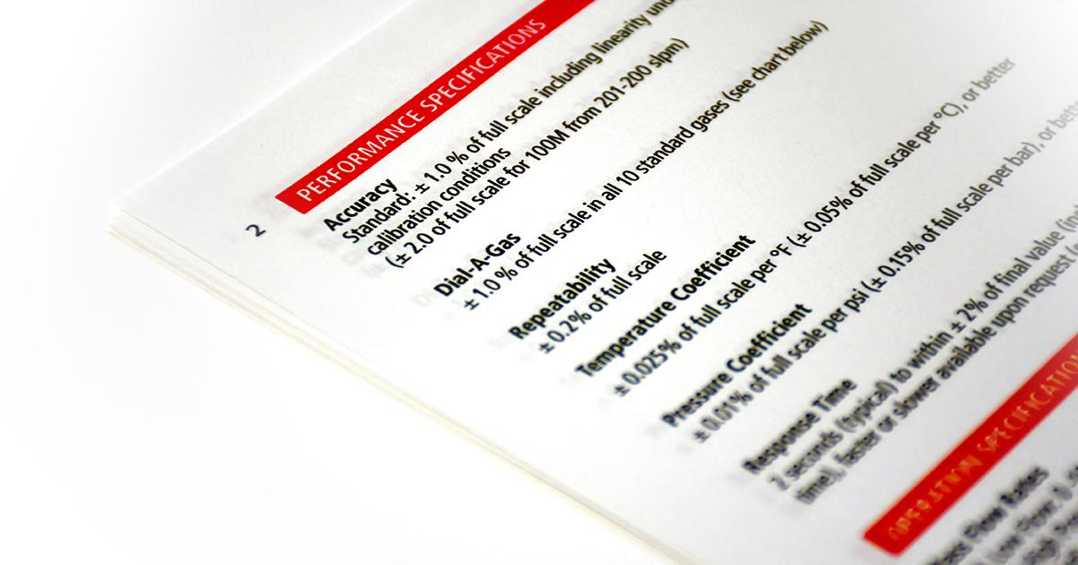
Dissecting a Mass Flow Meter Spec Sheet
7 Need to Know Terms for Successful Specification of a Mass Flow Meter or Controller
Whether you have been on the job for decades or just starting to purchase or specify a mass flow meter or controller to measure fluid flow in your application, there is key terminology to understand. Here are seven terms you should know to assure you are getting what you need to measure or control flow in your process effectively.
1. Flow Ranges (Mass Flow Rate)
The amount of fluid a mass flow meter or controller is best suited to measure flow for.
Example: the table below shows mass flow ranges of three typical flow body sizes of general purpose mass flow meters (MFM) and mass flow controllers (MFCs) for air at 0°C and 1 atmosphere pressure:
| Flow Body Size | Maximum Mass Flow Rate Range (slpm) |
| Low Flow | 0 to 50 |
| Medium Flow | 0 to 300 |
| High Flow | 0 to 1500 |
NOTE: Most manufacturers make no distinction between mass flow meters and controllers and published specifications may vary from manufacturer to manufacturer.
2. Accuracy
The accuracy statement on any spec sheet indicates how precise the flow meter/controller will measure flow within its flow ranges.
Officially, the American Society of Mechanical Engineers (ASME) defines the “accuracy” of flow meters as: the degree of freedom from error, or the degree of conformity of the indicated value of the instrument to the true value of the measured quantity [1].
An accuracy specification includes errors due to: (a) uncertainty in the flow calibration standard; (b) any non-repeatability of the MFM or MFC under test; (c) disagreement between the curve-fitting function and the actual flow response curve; and (d) inability of the flow calibration facility to deliver a sufficiently constant flow rate.
Typically, the accuracy of most general purpose MFMs and MFCs in measuring gas mass flow rate is 1% of full scale, including linearity, and at flow calibration conditions.
These are some examples of how manufacturers express the accuracy of their MFCs and MFMs in measuring mass flow rate:
- Percent of full scale: X % of full scale
- Combination: X % of reading + X % of full scale
- Divided range: X % of reading (≥ Y % of full scale) and X % of full scale (< Y % of full scale)
- Calibrated Span (%CS)
- Upper Range Limit (%URL)
3. Repeatability
The flow meter or controller’s ability to produce the same results/readings multiple times with no change in conditions (same flow rate, same operator/engineer, same laboratory, and short intervals of time, etc.).
Typically, the repeatability of general purpose MFMs and MFCs is +/-0.2% of full scale. Some manufacturers specify a repeatability of +/-0.2% of reading.
4. Reproducibility
The flowmeter’s ability to produce similar results/readings when the conditions of measurement differ. Example: different operators/engineers, facilities, time intervals, laboratories, etc.
5. Rangeability / Turn Down
Turndown or Rangeability is the range of flow (maximum to minimum flow rate) that a flow meter is able to measure in its specified accuracy.
6. Response Time
The time it takes the flow meter to settle on the new flow rate after a sudden change in flow.
7. Leak Integrity
The amount of gas leakage you can expect from seals on your mass flow meter or mass flow controller.
General purpose instruments with elastomeric seals have maximum leak-rate specifications ranging from about 1 x 10⁻⁹ to 5 x 10⁻⁹ atmosphere cubic centimeters per second of helium. Semiconductor MFCs and general purpose metal sealed MFMs and MFCs intended for vacuum processes have lower maximum leak rates of about 1 x 10-11 to 1 x 10⁻¹⁰ atmosphere cubic centimeters per second of helium.
This blog, as part of our ongoing core technology series based on excerpts from Sierra’s Founder and Chairman, Dr. John G. Olin’s, white paper entitled, “Capillary Tube Thermal Mass Flow Meters & Controllers – A User’s Guide,” dives “under the hood” and takes a closer look at the flow body, flow rates & sizing, and how flow conditioning works. Referenced material from ASME MFC-1M-2003(R2008), “Glossary of Terms Used in The Measurement of Fluid Flow in Pipes,” American Society of Mechanical Engineers, 3 Park Avenue, New York, NY.
Get more information on Capillary Tube Mass Flow Meters and Controllers:
Maryadine Washington, Mar-Com Manager
Sierra Instruments