Official Blog of Sierra--Let's Talk Flow!
Insertion Flow Meter Straight Run Requirements
You have specified the correct industrial Thermal insertion mass flow meter and received your brand new meter. Now what? Where do you install the meter for optimal performance? This is where technical expertise comes in, along with a mixture of science and tribal knowledge. In fact, Sierra has talked for years about a flowmeter being only as good as how it was calibrated, well, it’s also only as good as its installation. In our technical support department, the primary installation question we get is: How much upstream and downstream straight run is required and what happens if you use less straight run?
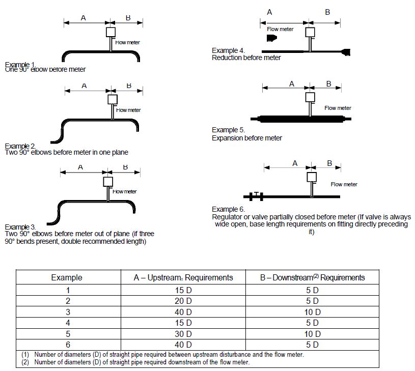
Select an installation site that will minimize possible distortion in the flow profile. This is because valves, elbows, control valves and other piping components may cause flow disturbances. Check your specific piping condition against the examples shown below. In order to achieve accurate and repeatable performance, install the flow meter using the recommended number of straight run pipe diameters upstream and downstream of the sensor. The chart below shows basic good plumbing practice for common upstream obstructions and meter locations.
 What happens if you use less run than recommended?
Remember first that a thermal insertion mass flow meter probe is a “point-velocity” device and is only as good as the installation. It measures a velocity at a single point and then the electronics multiply by the cross-sectional area to arrive at a flow rate.
The meter takes into consideration an average shape of the moving gas as it goes down the pipe. It assumes a fully-developed, bullet-shaped flow profile that is being measured at the highest velocity point at the leading edge, center.
In the case of an expansion fitting upstream (like Example 5 in the chart), the danger is a “jet-stream” of gas shooting through the new, larger diameter section, that has not yet spread out uniformly.
It is not possible to predict what will happen, nor to place a de-rated accuracy on the results. The results would most likely be noisy from the turbulent, tumbling gas. Again – can’t be exactly predicted.
My suggestion is to install it with 4/5 of the straight run ahead, and 1/5 after, and move the probe around, in and out, to come up with a map of the flow pattern. Hopefully, the largest flow will still be in the center, dropping off uniformly in both directions by about 15%.
Flow Conditioning is Optimal Solution
Another solution for insertion flow meters is to flow conditioning plates in flanges somewhere in the straight section, requiring 3 diameters of pipe run (2 before, 1 after). This installation will totally disrupt the flow, creating a “flat” profile. The center point is now representative of the entire flow and the meter will do a straight multiplication without accounting for a drop-off at the edges.
The best solution for constrained piping environments is to specify an inline thermal mass flow meter with integral flow conditioning elements inside the flange body. Watch this video to see how it works.
If this method is chosen, Sierra will calibrate the meter and flow conditioning all as one system assuring your readings will be more reliable and believable.
What are your biggest installation challenges? We would love to hear from you.
Jim Oswald, Technical Support Manager
Sierra Instruments

 Go to Autotest Division >
 DOWNLOAD
This was very helpful. Jim rocks.