Go to Autotest Division >
Understanding the Mass Flow Meter and Mass Flow Controller Flow Body – Why it Matters.
When it comes to mass flow meters and controllers size matters. Not all flow meters are the same. It’s like choosing a car. All cars are designed to move you from point A to B. However, if you live high up in the mountains you might want a truck or a tougher built car to handle your specific terrain.
The same applies when choosing a flow measurement device. If you need to measure water or steam you wouldn’t want to purchase a general purpose mass flow meter (MFM) or mass flow controller (MFC), you would want to look at an ultrasonic or vortex flow meter. If you need to measure gas for laboratory or research and development, you would look at mass flow meters and gas controllers.
However, like purchasing a car not all mass flow meters and controllers are built the same. It’s important to know how the MFC and MFM are built to know if it can handle your flow measurement application. In this part of the Core Technology Series, we will focus on the construct of an MFC or MFM flow body.
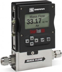
Flow Body
General purpose MFMs and MFCs typically have only three flow body sizes covering the entire flow range of the instruments---low flow, medium flow, and high flow. The type of flow device or flow controller you choose depends on your gas and the flow range.
| Flow Body Size | Maximum Mass Flow Rate Range (slpm) |
| Low flow |
0 to 50 |
| Medium flow |
0 to 300 |
| High flow |
0 to 1500 |
Low flow bodies often are machined out of a single piece of stainless steel bar stock. To get an idea of their relatively compact size, MFCs have the following approximate widths and lengths (not including inlet and outlet fittings): low flow---1.0 W x 3.0 L inches (25 W x 76 L mm); medium flow---1.5 W x 4.5 L inches (38 W x 114 L mm); and high flow---3.0 W x 9.0 L inches (76 W x 229 L mm). MFMs usually have the same widths but have about two-thirds the length in the medium and high flow sizes.
The flow body has inlet and outlet flow conduit fittings and houses the flow conditioning section, the sensor tube, the bypass/laminar flow element, and, in the case of MFCs, the control valve. The electronics are mounted in their enclosure on the top of the flow body. The wetted parts of a typical flow body and its internal components are made of corrosion resistant materials. Typical wetted materials for the flow bodies of general purpose MFMs and MFCs are: 316 L stainless steel; ferromagnetic stainless steel in the valve; and “O” rings and valve seats of fluoroelastomers and other advanced elastomeric materials. Some lower cost instruments intended for light duty and lower accuracy applications have flow bodies made of plastic or aluminum.
Instruments with elastomeric seals throughout the flow body have relatively low rates of leakage in and out of the flow body. MFMs and MFCs used in vacuum processes use metal seals at all locations in the flow body to further reduce leak rates. Manufacturers should subject every instrument to a helium leak check using a mass spectrometer leak detector, or equivalent instrument. Additionally, all instruments should comply with applicable pressurized equipment standards and codes, and manufacturers should pressure test all instruments to ensure compliance.
Process lines typically are tubes with outside diameters of 1/8, 1/4, 3/8, 1/2, 3/4, and 1 inche (6, 10, 12, and 20 mm). The 1/4 inch (6 mm) tubing size is most common. Some MFMs operated at very high flow rates are available in wafer and flange pipe sizes. Manufacturers offer a broad selection of process tube fittings, including compression fittings, elastomeric “O”-ring face seal fittings, and metal gasket face seal fittings. Since the inlet and outlet fittings contribute to the pressure drop in the instruments, the size of the fittings should be as large as practicable within constraints imposed by the size of the process line.
Semiconductor MFCs
Semiconductor MFCs often have a particulate filter, pressure regulator, and a positive shut-off valve installed upstream of the instrument and may have a positive shut-off valve and pressure regulator installed downstream. General purpose instruments also may include ancillary flow components in their installation.
Semiconductor MFCs used in the fabrication of high-end semiconductor devices have several special requirements to ensure that: (1) no particulates or other contaminants enter the fabrication process; (2) no toxic process gases escape the MFC; and (3) no ambient air enters the process. Typical specifications are: wetted surfaces must have high purity and be highly polished (surface roughness in the range of about 4 to 10 microinches Ra (0.1 to 0.25 micrometers Ra); leak rates must be extremely low; and internal flow paths, as shown in Fig. 3, must have no sharp corners, cavities, or dead spaces where particles can form. Semiconductor MFCs are available in both in-line and down- port configurations. Down-port versions reduce the axial dimensions of the MFC and its ancillary flow components, thereby facilitating the compactness required by manufacturers of semiconductor equipment.
This blog, as part of our ongoing core technology series based on excerpts from Sierra’s Founder and Chairman, Dr. John G. Olin’s, white paper entitled, “Capillary Tube Thermal Mass Flow Meters & Controllers – A User’s Guide,” dives “under the hood” and takes a closer look at the flow body, flow rates & sizing, and how flow conditioning works. Referenced material from ASME MFC-1M-2003(R2008), “Glossary of Terms Used in The Measurement of Fluid Flow in Pipes,” American Society of Mechanical Engineers, 3 Park Avenue, New York, NY.
Get more information on Capillary Tube Mass Flow Meters and Controllers: Download Dr. Olin’s Complete White Paper “Capillary Tube Thermal Mass Flow Meters & Controllers- A User’s Guide